Ideal for wind-energy applications


Overview
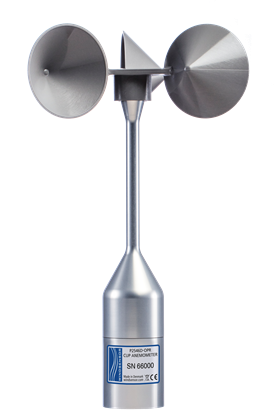
The P2546D, manufactured by WINDSENSOR, is a Class 1 cup anemometer commonly used in wind resource assessment and power performance applications. Each anemometer is individually calibrated compliant with IEC 61400-12-1 and is shipped with a MEASNET calibration certificate. The P2546D features permanent magnets mounted on the shaft that activate an electronic switching current. In response, this generates an output signal with a frequency that is proportional to the wind speed. The durable construction is suitable for both on-shore and off-shore environments. The “D” version of this sensor (electronic version) is compatible with all Campbell Scientific measurement and control data loggers.
Other available versions:
Benefits and Features
- One-piece rotor anemometer head (OPR)
- Durable construction with anodized aluminum and stainless steel
- Low threshold speed
- Short distance constant
- Negligible overspeeding
- Angular response independent of wind speed
- Fully tested temperature performance
- Symmetrical geometry
- No external power source
- MEASNET calibrated
Images

Similar Products
Specifications
| Sensor | 3-cup anemometer |
| Measurement Description | Wind speed |
| Range | 0 to 75 m/s |
| Starting Threshold | < 0.3 m/s |
| Starting Speed | 0.27 m/s |
| Gain | 0.6201 m |
| Distance Constant | λ0 = 1.81 ± 0.04 m |
| Standard Deviation of Offset | 0.014 m/s |
| Standard Deviation of Gain | 0.027 m |
| Variation among Units | ±1% |
| Non-Linearity | < 0.04 m/s |
| Temperature Influence | < 0.05 m/s (-15° to +60°C) |
| -NOTE- | The specifications are based on 80 wind tunnel calibrations performed according to the Measnet Cup Anemometer Calibration Procedure. The specified offset and gain figures represent the mean values of these calibrations. Variation among units designates the maximum deviation of any unit from the straight line representing these mean values. All units are run-in for 225 hours at 9 ms-1, in order to reduce the initial bearing friction to a level close to the steady state value. After run-in, bearing friction is tested at -15°C and at room temperature. The allowed limits for this test assure that the temperature influence on the calibration is within the specified limit. |
Calibration |
|
| Standard | U=A0+B0×f |
| Wind Speed | U [m/s] |
| Offset | A0=0.27 m/s ("starting speed") |
| Gain | B0=0.620 m |
| Output Frequency | f [Hz] |
Switching Characteristics |
|
| Signal Type | Potential free contact closure |
| Duty Cycle | 45% to 55% |
| Maximum Switching Voltage | 30 V |
| Maximum Recommended Switching Current | 10 mA |
| Series Resistance | 60 Ω |
| Operating Temperature Range | -40° to +60°C |
Documents
Brochures
Manuals
Frequently Asked Questions
Number of FAQs related to P2546D-L: 3
Expand AllCollapse All
-
Most Campbell Scientific sensors are available as an –L, which indicates a user-specified cable length. If a sensor is listed as an –LX model (where “X” is some other character), that sensor’s cable has a user-specified length, but it terminates with a specific connector for a unique system:
- An –LC model has a user-specified cable length for connection to an ET107, CS110, or retired Metdata1.
- An –LQ model has a user-specified cable length for connection to a RAWS-P weather station.
If a sensor does not have an –L or other –LX designation after the main model number, the sensor has a set cable length. The cable length is listed at the end of the Description field in the product’s Ordering information. For example, the 034B-ET model has a description of “Met One Wind Set for ET Station, 67 inch Cable.” Products with a set cable length terminate, as a default, with pigtails.
If a cable terminates with a special connector for a unique system, the end of the model number designates which system. For example, the 034B-ET model designates the sensor as a 034B for an ET107 system.
- –ET models terminate with the connector for an ET107 weather station.
- –ETM models terminate with the connector for an ET107 weather station, but they also include a special system mounting, which is often convenient when purchasing a replacement part.
- –QD models terminate with the connector for a RAWS-F Quick Deployment Station.
- –PW models terminate with the connector for a PWENC or pre-wired system.
-
Not every sensor has different cable termination options. The options available for a particular sensor can be checked by looking in two places in the Ordering information area of the sensor product page:
- Model number
- Cable Termination Options list
If a sensor is offered in an –ET, –ETM, –LC, –LQ, or –QD version, that option’s availability is reflected in the sensor model number. For example, the 034B is offered as the 034B-ET, 034B-ETM, 034B-LC, 034B-LQ, and 034B-QD.
All of the other cable termination options, if available, are listed on the Ordering information area of the sensor product page under “Cable Termination Options.” For example, the 034B-L Wind Set is offered with the –CWS, –PT, and –PW options, as shown in the Ordering information area of the 034B-L product page.
Note: As newer products are added to our inventory, typically, we will list multiple cable termination options under a single sensor model rather than creating multiple model numbers. For example, the HC2S3-L has a –C cable termination option for connecting it to a CS110 instead of offering an HC2S3-LC model.
-
Many Campbell Scientific sensors are available with different cable termination options. These options include the following:
- The –PT (–PT w/Tinned Wires) option is the default option and does not display on the product line as the other options do. The cable terminates in pigtails that connect directly to a data logger.
- In the –C (–C w/ET/CS110 Connector) option, the cable terminates in a connector that attaches to a CS110 Electric Field Meter or an ET-series weather station.
- In the –CWS (–CWS w/CWS900 Connector) option, the cable terminates in a connector that attaches to a CWS900-series interface. Connection to a CWS900-series interface allows the sensor to be used in a wireless sensor network.
- In the –PW (–PW w/Pre-Wire Connector) option, the cable terminates in a connector that attaches to a prewired enclosure.
- In the –RQ (–RQ w/RAWS Connector) option, the cable terminates in a connector that attaches to a RAWS-P Permanent Remote Automated Weather Station.
Note: The availability of cable termination options varies by sensor. For example, sensors may have none, two, or several options to choose from. If a desired option is not listed for a specific sensor, contact Campbell Scientific for assistance.
Privacy Policy Update
We've updated our privacy policy. Learn More
Cookie Consent
Update your cookie preferences. Update Cookie Preferences


