Connects many sensors to single data logger


Overview
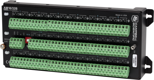
The AM16/32B multiplexer significantly increases the number of sensors that you can measure with a Campbell Scientific data logger. It interfaces with the data logger and adds terminals so that you can wire additional sensors of almost any type.
Read MoreBenefits and Features
- Significantly increases the number of sensors the data logger can measure
- Can multiplex 16, 32, or 48 sensors
- Supports many types of sensors including thermistors, potentiometers, strain gages, vibrating wires, reflectometers, and soil moisture blocks
- Decreases the cost of cabling individual sensors on long wire runs
- Allows a relay address to be used to go directly to a specific channel—reducing power consumption and wear on the relay switches
- Electrical surge protection via gas tubes on all analog I/O, and varistors or TVS diodes on all other connections
- Prevents sensor-cable damage by providing strain relief for sensor leads and independent routing for sensor shield lines
- Eliminates the requirement for dc blocking capacitors for gypsum soil moisture blocks, significantly reducing sensor cost
Note: The AM16/32B is not intended for high-speed measurements and should be used for measurement speeds of 30 seconds or slower. Using the AM16/32B for high-speed measurements may cause the relays to wear out more quickly and cause inaccurate measurements.
Images


CAD Files:
Detailed Description
Depending on sensor type, the AM16/32B can multiplex 16, 32, or 48 sensors. Up to six AM16/32Bs may be connected to the same data logger, depending on the number of control ports and analog inputs available.
The AM16/32B either multiplexes 16 groups of four lines (a total of 64 lines) through four common (COM) terminals. Alternatively, a manual switch setting allows the AM16/32B to multiplex 32 groups of two lines (also a total of 64 lines) through two COM terminals. A cable connects the common terminals to data logger analog inputs, excitation channels, or ground as required by the sensor. The data logger controls the multiplexer using two control ports, or one control port and one excitation channel.
Electrical Surge Protection
The equipment is protected from electrical surges using gas tubes on all inputs. A 35 V varistor is connected between the shield ground and ground lug to provide surge protection. The Reset, Clock, and +12 V terminals are protected by 18 V TVS diodes.
Specifications
| -NOTE- | The protection on the reset, clock, and +12 V inputs are provided by 18 V TVS diodes. |
| Power | Unregulated 9.6 to 16 Vdc |
| Scan Advance | Occurs on the leading edge of the clock pulse transition (from below 1.5 V to above 3.3 V) |
| Minimum Clock Pulse Width | 1 ms |
| Maximum Actuation Time for Relay | 20 ms |
| Relay Operation | Break before make |
| Initial Relay Resistance, Closed | 0.1 ohm |
| Maximum Switching Current |
500 mA (Switching currents greater than 30 mA [occasional 50 mA current is acceptable] will degrade the contact surfaces of the mechanical relays and increase their resistance.This will adversely affect the suitability of these relays to multiplex low voltage signals.Although a relay used in this manner no longer qualifies for low voltage measurement, it continues to be useful for switching currents in excess of 30 mA.) |
| Maximum Switching Voltage |
50 Vdc A voltage divider such as the VDIV10:1 may be needed between the AM16/32B and the data logger to stay within the input limits of the data logger channel. |
| Minimum Contact Life | 5 x 10⁷ operations |
| Maximum Contact Voltage Rating | 70 V |
| Maximum Voltage | 8 Vdc (clock level) |
| CE Compliance |
|
| Surge | Complies with IEC61000-4-5, test level 3 (±2 kV, 2 ohm coupling impedance) |
| Operating Temperature Range |
|
| Dimensions | 23.9 x 10.2 x 4.6 cm (9.4 x 4.0 x 1.8 in.) |
| Weight | ~680 g (~1.5 lb) |
ESD |
|
| Air Discharge | Complies with IEC61000-4-2, test level 4 (±15 kV). |
| Contact Discharge | Complies with IEC61000-4-2, test level 4 (±8 kV). |
Typical Current Drain |
|
| Quiescent | < 210 µA |
| Active |
|
Reset Levels |
|
| Inactive | < 0.9 V |
| Active | 3.3 to 8 V |
Compatibility
Note: The following shows notable compatibility information. It is not a comprehensive list of all compatible or incompatible products.
Data Loggers
| Product | Compatible | Note |
|---|---|---|
| 21X (retired) | ||
| CR10 (retired) | ||
| CR1000 (retired) | ||
| CR1000X (retired) | ||
| CR10X (retired) | ||
| CR200X (retired) | ||
| CR206X (retired) | ||
| CR211X (retired) | ||
| CR216X (retired) | ||
| CR23X (retired) | ||
| CR295X (retired) | ||
| CR300 (retired) | CRBasic programming experience is recommended, as the AM16/32B with the CR300 series is not currently supported in Short Cut. | |
| CR3000 (retired) | ||
| CR310 | CRBasic programming experience is recommended, as the AM16/32B with the CR300 series is not currently supported in Short Cut. | |
| CR350 | CRBasic programming experience is recommended, as the AM16/32B with the CR350 series is not currently supported in Short Cut. | |
| CR500 (retired) | ||
| CR5000 (retired) | ||
| CR510 (retired) | ||
| CR6 | ||
| CR800 (retired) | ||
| CR850 (retired) |
Mounting Equipment
| Product | Compatible | Note |
|---|---|---|
| ENC10/12 | Mounted sideways only. | |
| ENC10/12R | ||
| ENC12/14 | ||
| ENC14/16 | ||
| ENC16/18 | ||
| ENC24/30 | ||
| ENC24/30S |
Additional Compatibility Information
Data Logger Considerations
Programming
A series of data logger instructions control the AM16/32B operation (measurement instructions that are repetitive are generally contained within a programming loop; in the CR800-series, CR1000, CR3000, and CR5000, this functionality is available in the SubScan instruction).
Sensors
Compatible sensors include thermistors, potentiometers, load cells, strain gages, vibrating wire or vibrating strip transducers, water content reflectometers, and soil moisture blocks. The AM25T is recommended for multiplexing thermocouples.
Maximum Number of Sensor Connections
The maximum number of sensors multiplexed through one AM16/32B depends on the type(s) of sensors measured. For example, assuming identical sensors, the AM16/32B can multiplex up to:
- 32 single-ended or differential sensors that require two wires (for example, thermistors, half bridges)
- 16 single-ended or differential sensors that require four wires (for example, full bridges, four-wire half bridges)
- 32 vibrating wire sensors (16 with temperature) in conjunction with an AVW1, AVW4, AVW100, or AVW200-series Vibrating Wire Interface
- 48 half-bridge measurements (assumes common excitation and completion resistors at the data logger)
- 48 CS616 Water Content Reflectometers (assumes common excitation)
- 32 gypsum soil moisture blocks (model 223 or 253). The AM16/32B eliminates the requirement for dc blocking capacitors, significantly reducing sensor cost
Power Considerations
The AM16/32B draws less than 210 microamps quiescent, 6 milliamps active—so power considerations are heavily tied to the percentage of time in quiescent versus active states. Use of a relay address can reduce power consumption by minimizing the time spent in an active state.
In most applications, the data logger’s sealed rechargeable power supply should be more than sufficient; the data logger’s alkaline power supply could be used in applications where the multiplexer is activated infrequently.
Enclosure Considerations
The AM16/32B operates in most field conditions but requires a non-condensing environment. A weather-resistant enclosure equipped with desiccant is required for field use. A smaller enclosure is often used if the multiplexer is housed at a distance from the data logger.
If the AM16/32B is to be housed in the data logger’s enclosure, one AM16/32B, a CR800, CR850, CR1000, CR3000, or CR10X datalogger, and a PS150 power supply will fit in an ENC12/14. For convenience in wiring, a larger enclosure (e.g., ENC16/18) is recommended.
Software
LoggerNet, PC400, and ShortCut are compatible with the AM16/32B. Short Cut software (available at no charge from our website) supports simple programming and generates wiring diagrams for AM16/32B applications; early versions of Short Cut did not support multiplexers. Please reference the notes in the compatibility table for data loggers.
Documents
Brochures
Manuals
Compliance
Videos & Tutorials
Downloads
AM16/32B Example Programs v.1 (8 KB) 11-12-2020
CR6, CR1000X, and CR300 programs demonstrating taking multiple measurements using an AM16/32B relay multiplexer. Examples cover single-ended, differential, full-bridge (107 temperature sensor), and CS616 measurements.
Frequently Asked Questions
Number of FAQs related to AM16/32B: 12
Expand AllCollapse All
-
Make single-ended measurements, or use the AM16/32B multiplexer.
-
The mechanical contact relays of the AM16/32B are subject to corrosion and pitting, which leads to increased relay resistance and greater variations of the resistance with each contact cycle. Switched currents in excess of 30 mA degrade the relay contacts involved, rendering the channel unsuitable for further low-level analog measurements. (If an AM16/32 relay has been used for currents greater than 30 mA, it is not suitable for low-level mV measurements.) The switching of higher level currents causes increased corrosion and pitting of the relays. The solid-state relays on the AM25T multiplexer are not subject to corrosion and pitting; therefore, they are more suitable for low-level mV signals.
-
Yes. The 3WHB10K is required to measure three-wire temperature probes on the AM16/32B. As both RTDs and thermistors can be measured on the 3WHB10K, refer to the AM16/32B Relay Multiplexer Instruction Manual for the proper programming.
-
The number of switched lines and banks is different between the two multiplexers. The AM16/32B multiplexer has the operating option of running 16 banks of 4 lines each or of running 32 banks of 2 lines each. The AM25T multiplexer has only the one operating mode of 25 banks of 2 lines each. The 4x16 and 2x32 modes of the AM16/32B can offer more channels, convenience, and flexibility in applications than the 2x25-only mode of the AM25T multiplexer can. The 4x16 operation mode of the AM16/32B is a significant advantage for resistive bridge measurements to switch the current to the bridge circuits in addition to lines set up for the bridge output voltage. The 2x32 mode of the AM16/32B and the 2x25 mode of the AM25T multiplexer are commonly used for sensors that require no excitation (that is, voltages and thermocouples). In the 2x32 mode, the AM16/32B multiplexer has seven more channels than the AM25T offers.
-
Programming the AM25T multiplexer might be considered more convenient because the newer data loggers have a built-in AM25T CRBasic instruction to handle both AM25T differential thermocouple measurements and differential voltage measurements. There is no CRBasic built-in instruction for the AM16/32B multiplexer. However, the newer versions of the Short Cut program builder software have AM16/32B compatibility for a variety of different sensor types.
-
The differences between the mechanical relays on the AM16/32B and the solid-state relays on the AM25T are noteworthy with regard to switching time, voltage and current levels, power consumption, and relay activation noise.
- Solid-state relays switch faster than mechanical relays. The solid-state relays on the AM25T have a maximum activation time of less than 1 ms, whereas the slower AM16/32B mechanical relays have a maximum activation of 20 ms. This is an important aspect to consider in high sample rate applications of a large number of channels.
- The mechanical relays on the AM16/32B multiplexer are rated for handling higher voltage and current levels than the solid-state relays on the AM25T.
- The power consumption for the mechanical relays on the AM16/32B multiplexer is significantly greater than that of the solid-state relays on the AM25T.
- The mechanical relays on the AM16/32B multiplexer make a distinct clicking sound when closing. In contrast, the solid-state relays on an AM25T are silent. The sound of mechanical relays may be annoying to humans or animals at the installation site. In some applications, the clicking sound of the relays can be a beneficial indicator that measurements are being performed.
-
The AM25T multiplexer has a built-in PRT temperature bridge circuit for accurate thermocouple cold junction compensation. It also has heat stabilization features designed to minimize temperature gradients across the wiring panel. The AM25T incorporates a large amount of thermal mass in a central concentrated area around the wiring panel terminals. The wiring terminals on the AM25T are located close to each other and close to the heat stabilization mass.
On the AM16/32B multiplexer, the wiring panel terminals are spread out across a larger area and do not have the large thermal mass design around the terminals that the AM25T has. Part of the thermal mass includes a heat bar that runs under the wiring panel connectors of which the PRT reference element is coupled to. The PRT element is incorporated into a precision full bridge circuit and calibrated for accurate reference temperature readings. The AM16/32B multiplexer does not have a built-in reference temperature PRT and heat bar design. When using AM16/32B multiplexers for thermocouple measurements, an external reference temperature measurement will need to be provided.
Because of its built-in reference temperature circuit and thermal stabilization features, the AM25T multiplexer is more suitable for thermocouple measurements.
-
Two multiplexers, each with a maximum of 16 or 32 sensors per multiplexer, can be attached. If temperature measurements are excluded from each sensor, 32 sensors are possible.
-
A practical maximum is to connect one multiplexer per every two control terminals on the data logger. Control terminals can be shared between multiplexers to increase the number of connected multiplexers. Sharing terminals, however, requires more complex wiring and programming. Users who would like to connect more than one multiplexer per every two control terminals are advised to contact a sales or support engineer at Campbell Scientific for assistance.
Case Studies
The Expressway S19 represents a critical link in Europe’s transportation network, stretching 570 km (354.2......read more
Overview The reconstruction of the navigational lock system at the Iron Gate I Hydroelectric Power Station......read more
Agrivoltaics or dual-use solar is a system combining an agricultural crop (viticulture, arboriculture, field crops,......read more
The drawings and engravings of the Chauvet Cave not only demonstrate an exceptional artistic and......read more
The Delaware Department of Transportation (DelDOT) notified Intelligent Infrastructure Systems (IIS) and Pennoni of the......read more
Intelligent Infrastructure Systems, a Pennoni company, was contracted to design and install an efficient structural-health......read more
In April of 2015, Sandia National Laboratories (SNL) contracted with Montrose Air Quality Services (MAQS)......read more
The Problem—How to optimize green-roof performance The University of Toronto's Green Roof Innovation Testing Laboratory (GRIT......read more
Articles and Press Releases
Privacy Policy Update
We've updated our privacy policy. Learn More
Cookie Consent
Update your cookie preferences. Update Cookie Preferences


