Overview
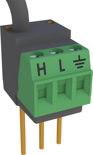
The 4WFBS120 is a four-wire, full-bridge module that provides completion resistors for a strain gage or other sensor that acts as a single variable resistor. This module should be used to measure sensors that have a 120-ohm nominal resistance.
Read MoreBenefits and Features
- Easy to install or remove
- Connects directly into data logger input terminals
- Compatible with most Campbell Scientific data loggers
Images

Similar Products
Detailed Description
The 4WFBS120 completes a full Wheatstone bridge. It can also be used to complete the back half of a Wheatstone bridge for use in a ¼ bridge strain circuit (one active element) using a dummy gage, or in a ½ bridge strain circuit (two active elements). The Wheatstone bridge circuit converts small changes in resistance to an output voltage that our data loggers can measure.
The 4WFBS120 includes two external pins that allow customers to perform shunt calibrations, which are used to correct for sensitivity errors.
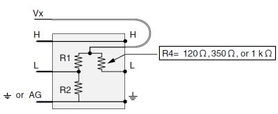
4-Wire Full Bridge Module Schematic
(R4=120 Ω for the 4WFBS120)

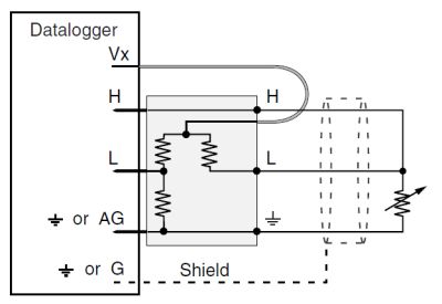
4WFBS120-to-Sensor Hookup

Specifications
| Used With | 4-wire strain gages or other full bridge measurements that have a 120 Ω nominal resistance |
| Dimensions | 1.5 x 1.5 x 2.7 cm (0.6 x 0.6 x 1.0 in.) for body with prongs |
| Weight | 6 g (0.2 oz) |
2:1 Resistive Divider |
|
| Resistance | 1 kΩ/1 kΩ |
| Tolerance | Ratio: ±0.01% (@ 25°C) |
| Maximum Temperature Coefficient | Ratio: 0.5 ppm/°C (-55° to +85°C) |
| Power Rating | 0.1 W (@ 70°C) per element |
Completion Resistor (bulk metal foil) |
|
| Resistance | 120 Ω |
| Tolerance | ±0.01% (@ 25°C) |
| Maximum Temperature Coefficient | 0.8 ppm/°C |
| Power Rating | 0.25 W (@ 70°C) |
Compatibility
Note: The following shows notable compatibility information. It is not a comprehensive list of all compatible or incompatible products.
Data Loggers
| Product | Compatible | Note |
|---|---|---|
| 21X (retired) | ||
| CR10 (retired) | ||
| CR1000 (retired) | ||
| CR10X (retired) | ||
| CR200X (retired) | ||
| CR206X (retired) | ||
| CR211X (retired) | ||
| CR216X (retired) | ||
| CR23X (retired) | ||
| CR295X (retired) | ||
| CR300 (retired) | ||
| CR3000 (retired) | ||
| CR310 | ||
| CR350 | ||
| CR500 (retired) | ||
| CR5000 (retired) | ||
| CR510 (retired) | ||
| CR6 | ||
| CR800 (retired) | ||
| CR850 (retired) |
Miscellaneous
| Product | Compatible | Note |
|---|---|---|
| CR9050 (retired) |
Additional Compatibility Information
Multiplexers
The 4WFBS120 is compatible with our multiplexers.
Data Logger Considerations
The 4WFBS120 uses one differential analog input; an adjacent analog ground channel accepts the "ground prong" of the 4WFBS120. Not all data logger terminal strips have this sequence on all channels, so please check your data logger's wiring panel to confirm channel assignments, especially if you plan to use multiple Terminal Input Modules.
The lead wire that emanates from the head of the 4WFBS120 connects to a data logger excitation channel.
Please note that if a CR10X will be used to measure thermocouples in the same application, newer CR10X Wiring Panels and the CR10XTCR Reference Thermistor (with its accompanying Thermocouple Cover) are deep enough to cover the data logger input channels with a Terminal Input Module attached; older CR10TCRs are not deep enough.
Programming
The 4WFBS120 is measured with the BrFull Instruction in CRBasic, and with Instruction 6 (Full Bridge) in Edlog.
Documents
Frequently Asked Questions
Number of FAQs related to 4WFBS120: 5
Expand AllCollapse All
Privacy Policy Update
We've updated our privacy policy. Learn More
Cookie Consent
Update your cookie preferences. Update Cookie Preferences


